Wiring Proximity Switches to Isolated Digital Inputs
1. Proximity Switch Connections and Functions
Proximity switches are on/off devices widely used in industry for sensing the presence of metallic or non-metallic objects. They have become standardized, making them easy to interface to isolated digital inputs on PLC's, and the CSA/UL certified ADU Relay I/O Interface Products. Output wires follow a standardized colour code where BROWN is the sensor power (12-24VDC), BLACK is the N.O. output signal, and BLUE is the sensor ground connection. Four-wire versions also provide a WHITE wire, which is a N.C. output that compliments the N.O. output. The three-wire version is the most common and is shown in Figure 1 with simplified schematic diagrams for the two output types. NPN output types provide an OUTPUT connection to GND when an object is sensed, and PNP types provide an OUTPUT connection to sensor power (12-24VDC) when an object is sensed.

Figure 1 : 3-Wire Proximity Switch Simplified Schematic Diagrams
Less common two-wire proximity switches operate without a separate output signal. When connected in series with appropriate DC power and a load, they draw a very low OFF-state current, typically less than 1mA which is just enough to power the sensors internal circuitry. When a target is detected, internal circuitry increases the current draw to up to several hundred milliamps. Although they are not specifically designed to be connected to isolated digital inputs on PLC's, they can be connected if certain provisions are made.
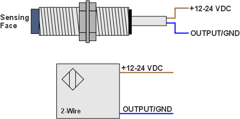
Figure 2 : 2-Wire Proximity Switch Simplified Schematic Diagram
2. Isolated Digital Input Circuitry
Isolated digital inputs on PLC's are provided in groups with an associated separate common connection. The CSA/UL Certified ADU USB Relay I/O Interface Products, feature two, 4-bit isolated digital input ports with the exception of the ADU200 which has one 4-bit input port. Regardless of the model number, the isolated digital input circuitry on all ADU products is identical. For our examples below we will use an ADU228 Solid-State USB Relay I/O Interface.
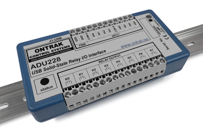
Figure 3 : ADU228 USB Solid-State Relay I/O Interface
Isolated digital inputs generally use bi-directional optocouplers with an associated current limit resistor for each line to obtain isolation as shown in Figure 4. The use of bi-directional optocouplers enable the use of either polarity of input signal. The COMA connection can either be connected to ground, or the VDC supply (12-24VDC). When COMA is connected to ground, VDC supply voltages on individual inputs will energize the input. When COMA is connected to VDC, GND connections to individual inputs will energize the input.
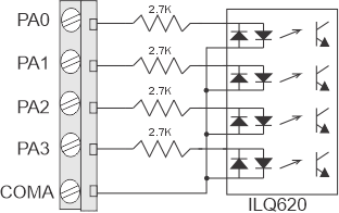
Figure 4 : PLC Isolated Digital Input Simplified Schematic Diagram
3. Wiring 3-Wire Proximity Switches
To connect 3-wire NPN proximity switches to isolated digital inputs, connect the VDC supply to the COMA input, and the OUTPUT wire to an individual digital input line as shown in Figure 5. When the proximity switch detects an object, the OUTPUT will energize and internally connect the GND to the OUTPUT wire allowing current to flow from the VDC source into COMA and out of the PA0 line, which energizes the input.
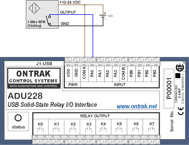
Figure 5 : Wiring 3-Wire NPN Proximity Switches
To connect 3-wire PNP proximity switches to isolated digital inputs, connect the GND to the COMA input, and the OUTPUT wire to an individual digital input line as shown in Figure 6. When the proximity switch detects an object, the OUTPUT will energize and internally connect the VDC to the OUTPUT wire allowing current to flow from the VDC source into PA0 and out of the COMA line, which energizes the input.
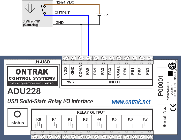
Figure 6 : Wiring 3-Wire PNP Proximity Switches
4. Wiring 2-Wire Proximity Switches
Two-wire proximity switches were not designed to be connected to isolated digital inputs. They were designed to be used with direct connection to loads without the use of a PLC or other control devices. Loads such as solenoids can be connected directly in series with two-wire sensors and a suitable DC power supply as shown in Figure 7. When no object is sensed and the sensor is OFF state, only a small "bleed current" flows through the output circuit to power its internal circuits (typically less than 1mA) which is not enough to energize the solenoid. When an object is sensed, the sensor increases its current draw to hundreds of mA, which activates the solenoid.
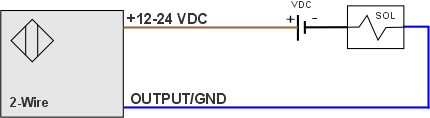
Figure 7 : 2-Wire Proximity Switch Connection to Solenoid
Isolated digital inputs on PLC's are sensitive and can be energized by the small 1mA current that flows through a two-wire proximity switch when the sensor is in its de-energized (OFF) state. This results in a digital input being energized whether or not anything is detected by the two-wire proximity switch. Provision must be made for the sensor OFF state "bleed current" to enable connection to an isolated digital input. This comes in the form of a "Bleed Resistor" connected from COMA to the digital input to provide a path for this bleed current to flow without energizing the digital input as shown in Figure 8. A 1000 OHM, 2-WATT resistor works best for sensors with 1mA or less of bleed current. This is because the optocoupler input photodiodes need at least 1.1V to start to turn on. The bleed resistor will allow the 1mA to flow and only cause a 1V drop accross it, which is not enough to start to turn on the digital input. To test your sensor setup, measure across the bleed resistor when the sensor is in the OFF state, and ensure the voltage drop is 1V or less.
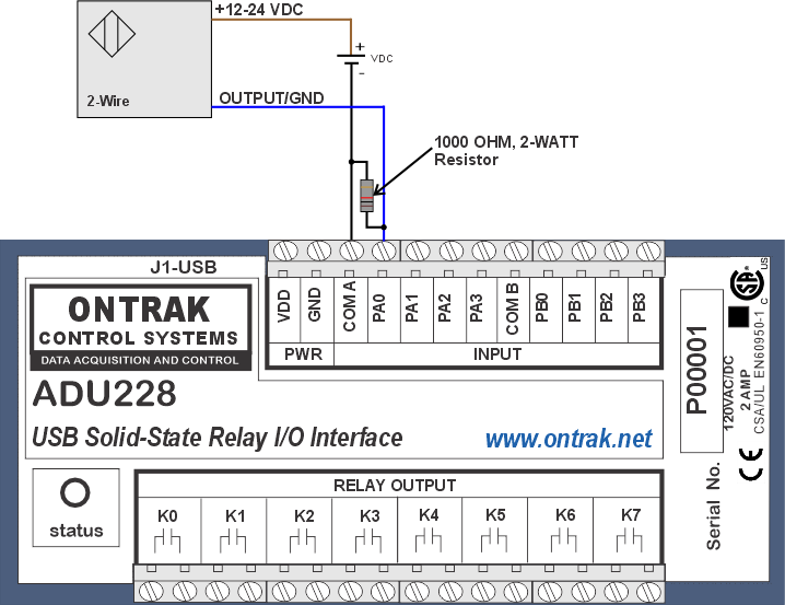
Figure 8 : 2-Wire Proximity Switch Connection to Digital Input With Bleed Resistor
5. Caveats
1. Bleed Resistor wattage must be 2 Watts or greater because almost all the VDC supply appears across the resistor when the sensor is energized.2. PLC's and ADU's use cage-clamp style terminal blocks. Care must be taken when connecting more that one wire to a single terminal. Ensure only wires of the same gauge, and type (solid/stranded), are ganged to a single terminal.
3. Make no connection to the GND or VDD terminals of your ADU device when connecting proximity switches. The VDD and GND outputs are for the "wetting" of dry contacts only.
4. Each 4-bit digital input port supports up to four proximity switches of the same type (NPN or PNP). Do not connect both NPN and PNP proximity switches to the same digital input port. This is why isolated digital input ports are separated into two 4-bit ports instead of one 8-bit port.