MLPC laser Controller V 3.2
The MLPC laser controller is a novel design that achieves first pulse suppression by precision control of the modulator pulse amplitude to compensate for the state of the population inversion in the laser medium. The controller operates in standard single pulse, pulse burst, and continuous modes with fiber laser pulse rates of up to 30MHz and trigger rates up to 1MHz. The controller is described by patent Laser Control System and method WO 2015/006867 Al authored by Darren Kraemer and Tom Fortin.
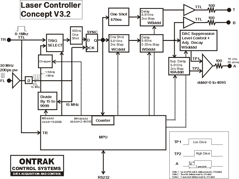
INPUT and OUTPUT Connections
TR - TTL level input used to apply external trigger pulses or gate signals. MAX input 5V ( protected)
FL - Fiber Laser Input Sync. 50 ohm impedance, 30MHz nominal, 100ps minimum width, 100mV minimum amplitude. MAX input 5V
T - TTL ( through 100 ohms ) aux output. 670ns pulse delayed from 5-510ns from start of A signal.
A - Modulator drive signal. 1V into 50 ohms. Synced with FL input (50ps jitter max)
B - TTL ( through 100 ohms ) eq. of Modulator drive signal.
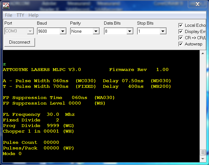
Screen shot of status screen in terminal mode. Use Z<cr> to view
Commands:
WAnnn Suppression delay time ( burst ) 15-255 2ns per step
WBnnn T delay time 0-255 2ns per step
WCnnn A pulse width time 0-255 2ns per step
WDnnn A phase delay 0-255 0.25ns per step
WGnnnn Sets programmable divide ratio. Range 15-9999 results in Freq range 1MHz down to 1.5KHz
WPnnnnn Sets number of pulses in each packet. Range 0 to 65535
WSnnnn Sets suppression voltage level. Range 0-4095 ...4095 is max suppression.
WHnnnnn Sets chopper rate. Range 2 to 65535 (1 in 2 to 1 in 65535)
RA Returns suppression delay time ( burst ) 015-255 2ns per step
RB Returns T delay time 000-255 2ns per step
RC Returns A pulse width time 000-255 2ns per step
RD Returns A phase delay 000-255 0.25ns per step
RG Returns programmable divide ratio. Range 00015-09999 Freq range 1MHz down to 1.5KHz
RP Returns number of pulses in each packet. Range 00000 to 65535
RS Returns suppression voltage level. Range 0000-4095 ...4095 is max suppression.
RH Returns chopper rate. Range 00001 to 65535 (1 in 1 to 1 in 65535)
RV Returns current software revision as a three digit number. Ex. 100
RF Returns FL input frequency in MHz. Ex. 30.0
RM Returns present mode. range 0-7
MODES OF OPERATION
M0 All Outputs OFF
M1 Single Pulse Mode-External Trigger
M2 Single Pulse Mode-Internal Trigger
M3 Packet Mode-Internal Trigger
M4 Packet Mode-External Trigger
M5 External Gate Mode-( TR input used to gate internal trigger output pulse generation.)
M6 External Trigger with FP Suppression
M7 External Trigger with Constant Amplitude Control.
G Go command. Starts operation determined by mode.
S Stop command . Stops operation.
Z Shows status screen
Block Write Format
( TBD )
Block Read Format
( TBD )
Notes:
1. Single-pulse is any pulse less than 40ns ( usually 38ns )
2. Burst-pulse is any pulse 40ns or greater.
3. Packet is a group of pulses ( single or burst ) ( mode 3 or 4 )
5. Chopper Mode functional only with Internal Trigger modes ( Modes 2, 3, 4 and 5 )
6. Do not change variables unless controller is in the stopped condition.
7. LED is GREEN when in stopped condition, and RED when in run condition.
To Operate....
1. Set all delay, count and suppression variables
2. Set mode using Mn where n is mode number ( 0-7 ).
3. G command to run, S command to stop.
4. Mode 3 is retriggerable.
5. Once first G command is received in Mode 3 , additional packets can be generated with a CR ( 0Dh) input.
M0 All Outputs OFF
In this mode all outputs are off and all inputs will be unresponsive to external stimulus.
M1 Single Pulse Mode-External Trigger
In this mode a single pulse ( 15-39ns ) or burst ( 40-300ns ) is generated for every rising edge on the TR input connection. The maximum recommended input frequency is 1MHz. The input will stop pulse generation at approx. 1.3MHZ.
Output pulse is synced to FL input with jitter of less than 50ps. ( as in all modes of operation )
If suppression is used with a single pulse mode setting ( 15-39ns ), suppression must be reset before each G command. Suppression does not require reloading if pulse width is set to 40ns or higher.
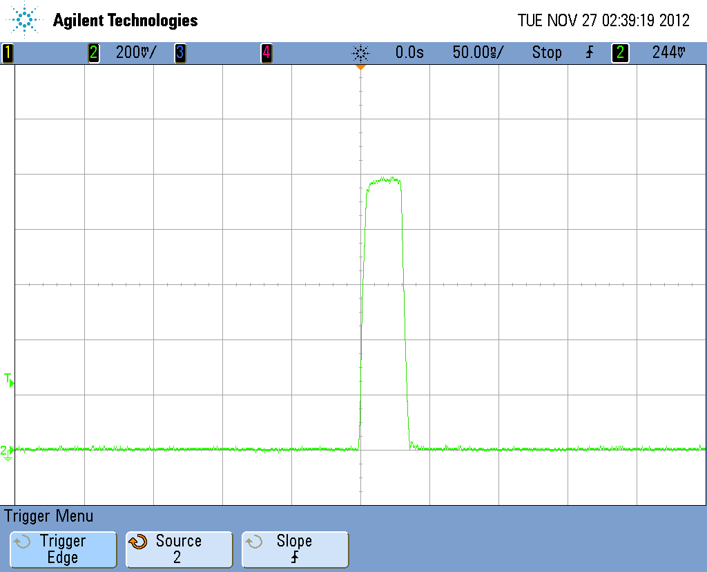
Figure 1- Mode1 30ns pulse. Amplitude 1V into 50 ohms.
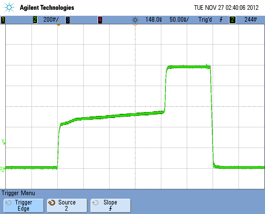
Figure 2- Mode1 300ns pulse ( WC150 ). Suppression Time 210ns ( WA105 ). Suppression level 4000 (WS4000).
The rate of amplitude increase is set by on-board resistors and setting depends on the population inversion time of PA.
M2 Single Pulse Mode-Internal Trigger
Mode 2 operates with the same parameters as Mode 1 except the trigger pulses are generated internally by dividing the FL input frequency which is a nominal 30MHz. No connection to the external trigger is required for this mode.
The FL input nominal frequency of 30MHz input is divided by 2 to give an internal clock of 15MHZ. This clock is then divided by the value set using the WG command where WG15 results in 1MHZ ( maximum ) repetition rate, and WG9999 results in a 1.5KHz ( minimum ) repetition rate.
For lower pulse repetition rates see the CHOPPER section below.
Pulse generation is started using the G command and stopped using the S command.
M3 Packet Mode-Internal Trigger
Mode 3 generates packets of pulses ( or bursts) under software control using the internal trigger.
The number of pulses per packet is set using the WP command with a range of 1 to 65535 pulses/packet.
If suppression is used, it is re-enabled for each packet.
Packets are generated by first loading all timing parameters and then every time a G command is received by the interface a packet will be generated.
Packet counts are accurate at rep rates of 750KHz and below. At 750KHz to 1MHz rep rates, packet accuracy is 0+1 count.
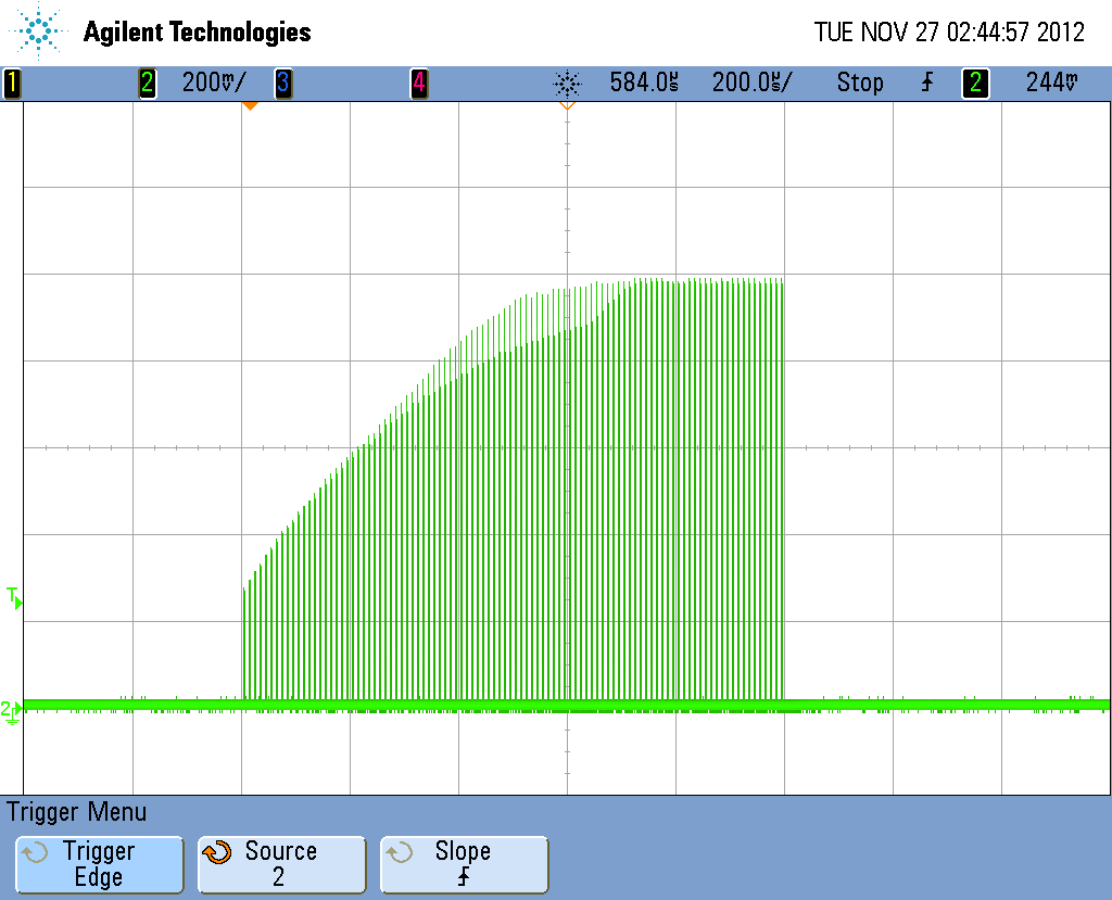
Figure 3 - Mode 3 WC15 ( 30ns ) , WS4000, WP100 ( 100 pulses/packet), WG150 ( 100 KHz rep rate )
Note that anomaly in waveform is simply due to sampling of digital oscilloscope.
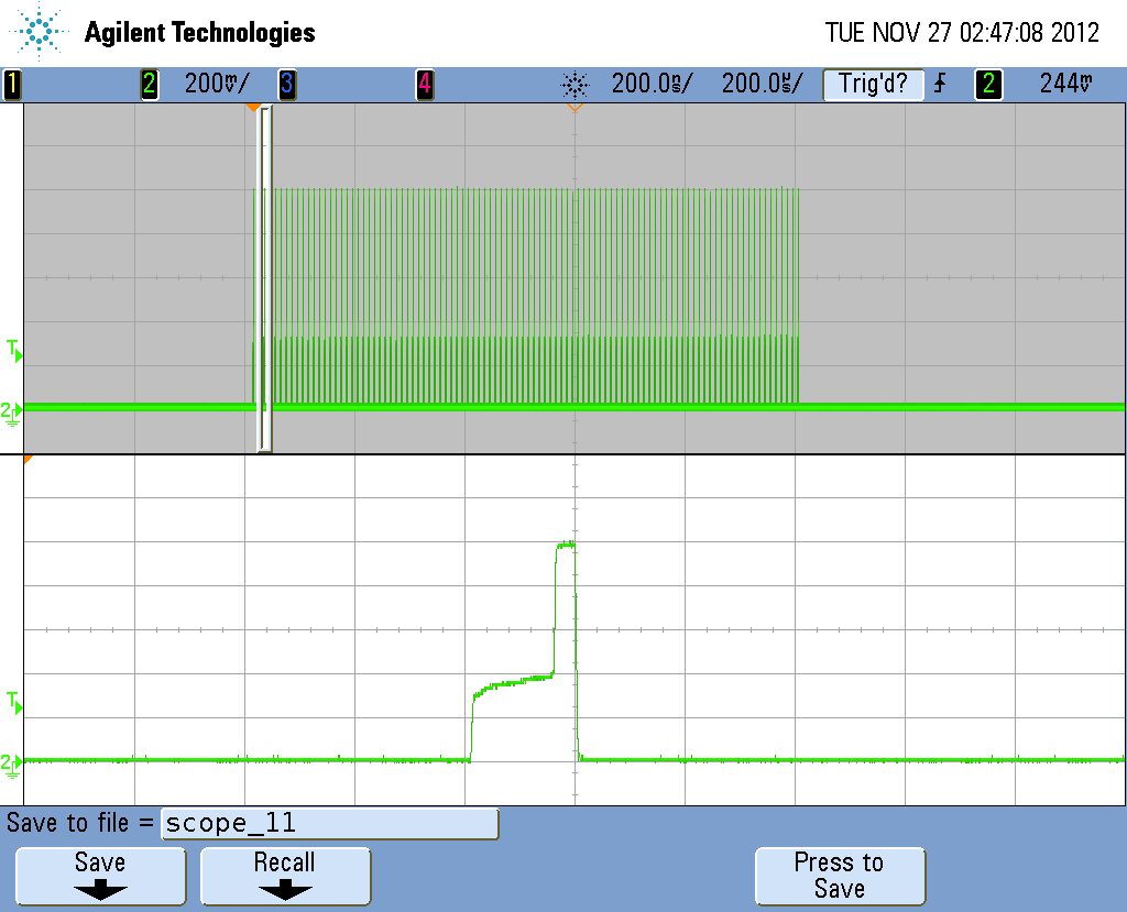
Figure 4 - Mode 3 WC100 ( 200ns ) ,WA75 ( 150ns ) WS4000, WP100 ( 100 pulses/packet), WG150 ( 100 KHz rep rate )
Zoom shows single burst in packet
M4 Packet Mode-External Trigger.
In mode 4, packets are generated every time a rising edge on the TR input occurs.
If single pulses ( 15-39ns ) are used with suppression, the suppression is re-enabled on each packet.
The maximum recommended packet frequency is 100KHz and consideration for the length of packets should be made to avoid overlap. ( See Figures 8a, 8b, 8c and 8d which show packets as the trigger rate causes overlap. As overlap begins the suppression level will be reduced proportionally)
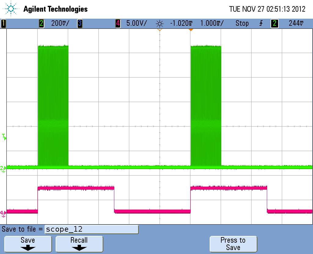
Figure 5 - WC100 ( 200ns burst ), WA75 ( 150ns suppression time ), WS4000 ( Suppression level of 4000 )
WG150 ( 100KHz rep rate ), WP100 ( 100 pulse packets )
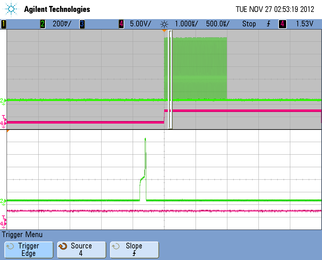
Figure 6 - WC100 ( 200ns burst ), WA75 ( 150ns suppression time ), WS4000 ( Suppression level of 4000 )
WG150 ( 100KHz rep rate ), WP100 ( 100 pulse packets ) ZOOMED
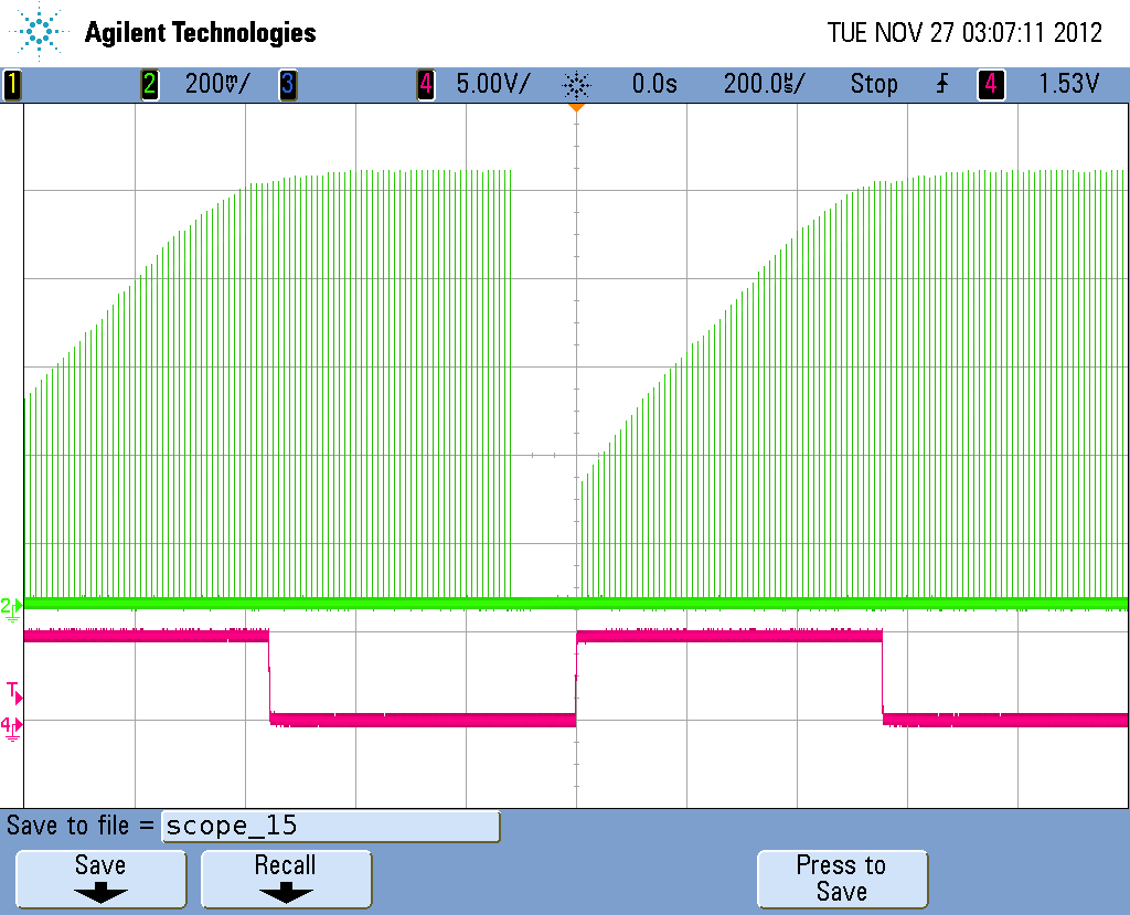
Figure 7 - WC15 ( 30ns pulse ), WS4000 ( Suppression level of 4000 )
WG150 ( 100KHz rep rate ), WP100 ( 100 pulse packets )
Figure 8a - WC15 ( 30ns pulse ), WS4000 ( Suppression level of 4000 )
WG150 ( 100KHz rep rate ), WP100 ( 100 pulse packets )
Rep rate of 900Hz
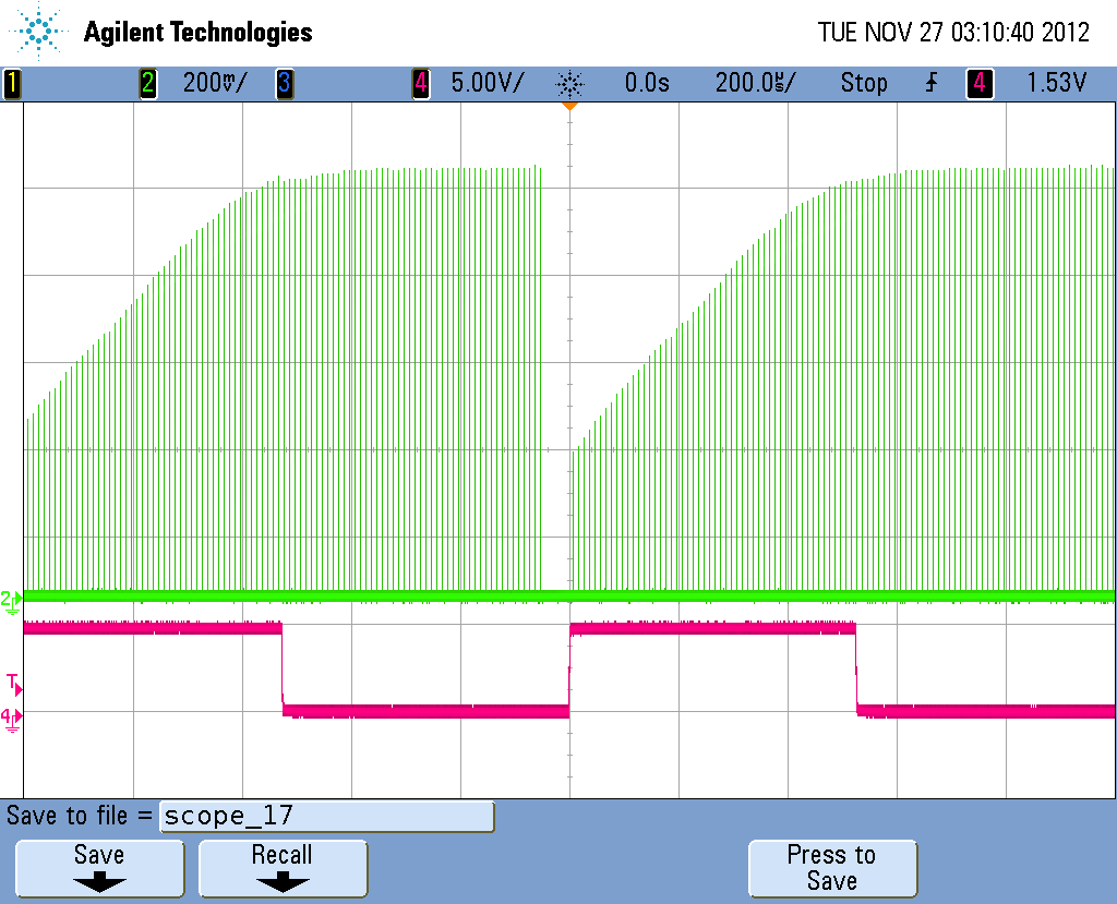
Figure 8b - WC15 ( 30ns pulse ), WS4000 ( Suppression level of 4000 )
WG150 ( 100KHz rep rate ), WP100 ( 100 pulse packets )
Rep rate of 950Hz
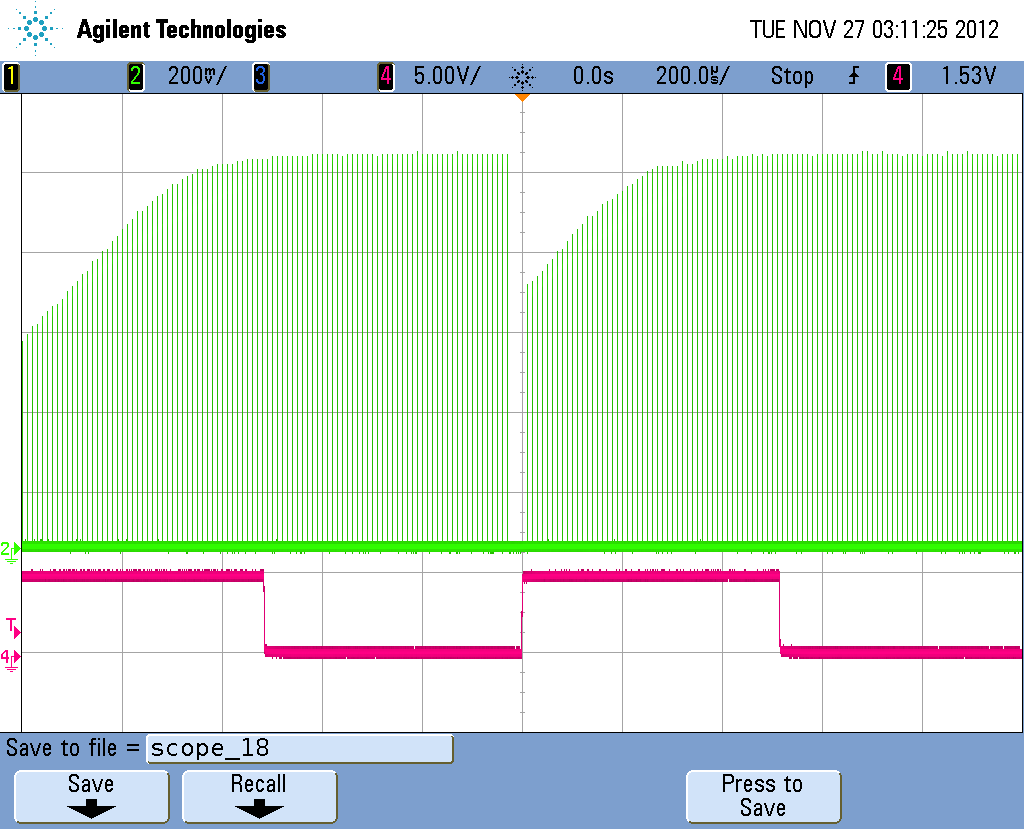
Figure 8c - WC15 ( 30ns pulse ), WS4000 ( Suppression level of 4000 )
WG150 ( 100KHz rep rate ), WP100 ( 100 pulse packets )
Rep rate of 970Hz
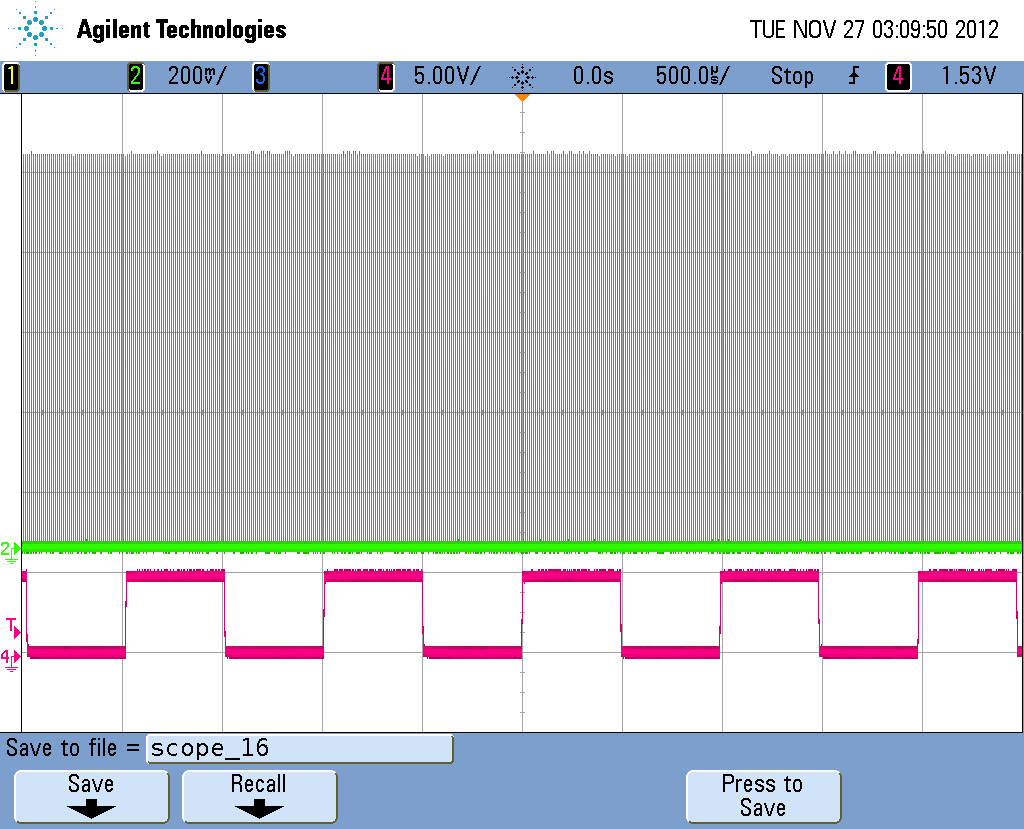
Figure 8d - WC15 ( 30ns pulse ), WS4000 ( Suppression level of 4000 )
WG150 ( 100KHz rep rate ), WP100 ( 100 pulse packets )
Rep rate of 1000Hz ( full overlap)
M5 External Gate Mode- ( TR input used to gate internal trigger output pulse generation.)
Mode 5 gates output pulses when the TR input is HIGH.
When gate pulse goes low it must remain low for a minimum of 40us to allow suppression values to be reloaded for next gate.
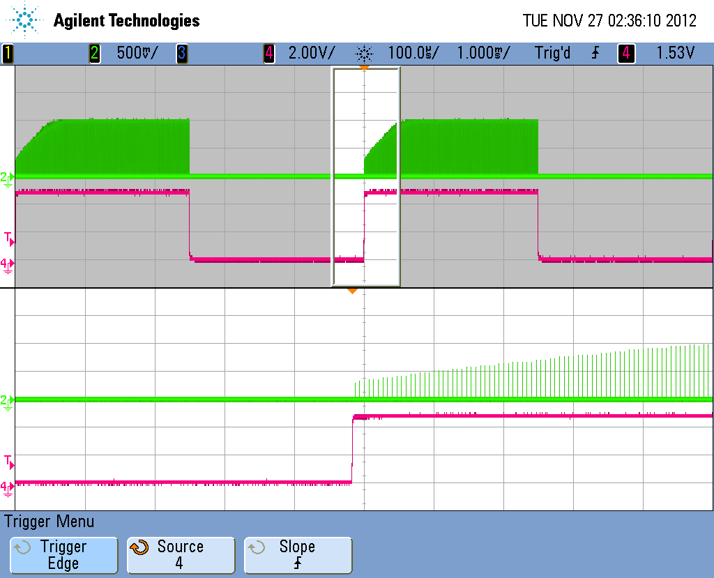
Figure 9 - WC15 ( 30ns pulse ), WS4000 ( Suppression level of 4000 )
WG100 ( 150KHz rep rate ), Gate Signal 200HZ at 50% Duty Cycle
Zoomed to show suppression details.
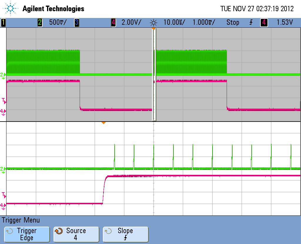
Figure 10 - WC150 ( 300ns pulse ), WA100 ( 200ns suppression time) WS4000 ( Suppression level of 4000 )
WG100 ( 150KHz rep rate ), Gate Signal 200HZ at 50% Duty Cycle
Zoomed to show suppression details.
M6 External Trigger with FP Suppression
Mode 6 is a special mode for use with single pulses ( 15-39ns ) only. In this mode the user applies trigger pulses to the TR input to generate output pulses with suppression mode constantly enabled. The TR input trigger frequency can range from 1MHz down to 10KHz. As packets of trigger pulses are applied, suppression will occur at the start of each pulse sequence. A minimum time with no trigger pulses of 200us will re-enable the suppression parameters.
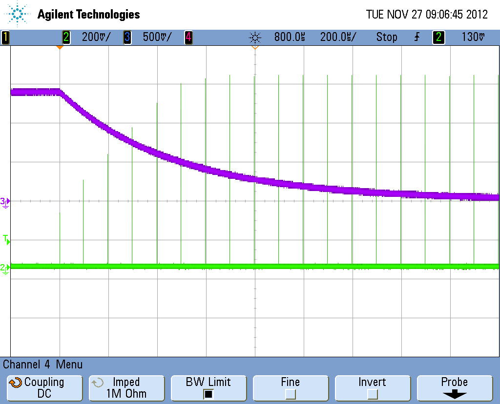
Figure 11 - WC15 ( 30ns pulse ), WS4000 ( Suppression level of 4000 )
10KHz external trigger applied, Purple trace shows suppression voltage.
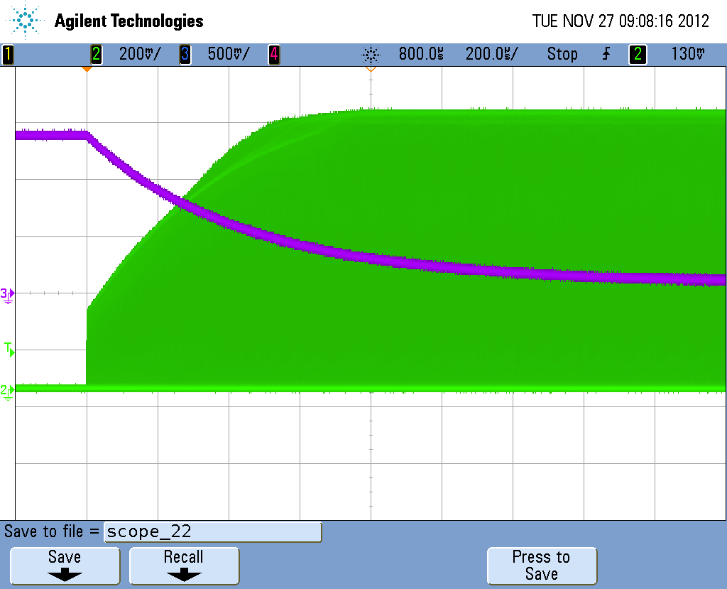
Figure 12 - WC15 ( 30ns pulse ), WS4000 ( Suppression level of 4000 )
1MHz external trigger applied, Purple trace shows suppression voltage.
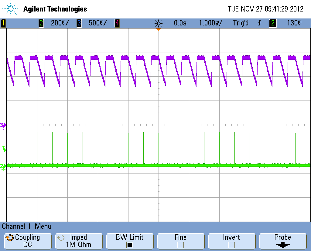
Figure 13 - WC15 ( 30ns pulse ), WS4000 ( Suppression level of 4000 )
2KHz external trigger applied, Purple trace shows suppression voltage.
Do not use this mode. It is shown for explanation purposes only.
M7 External Trigger with Constant Amplitude Control.
Mode 7 is another special mode for use with single pulses ( 15-39ns ) only. In this mode the user applies trigger pulses to the TR input to generate output pulses with a constant amplitude determined by suppression voltage. The TR input trigger frequency can range from 1MHz down to 1Hz, however, would generally be used for frequencies from 10KHz down to 0 Hz.
This mode is useful for users operating at rep rates of 10KHz and less, as at these rates the population inversion in the PA is at maximum for each pulse. This gives a very precise way to control output power at these low rates.
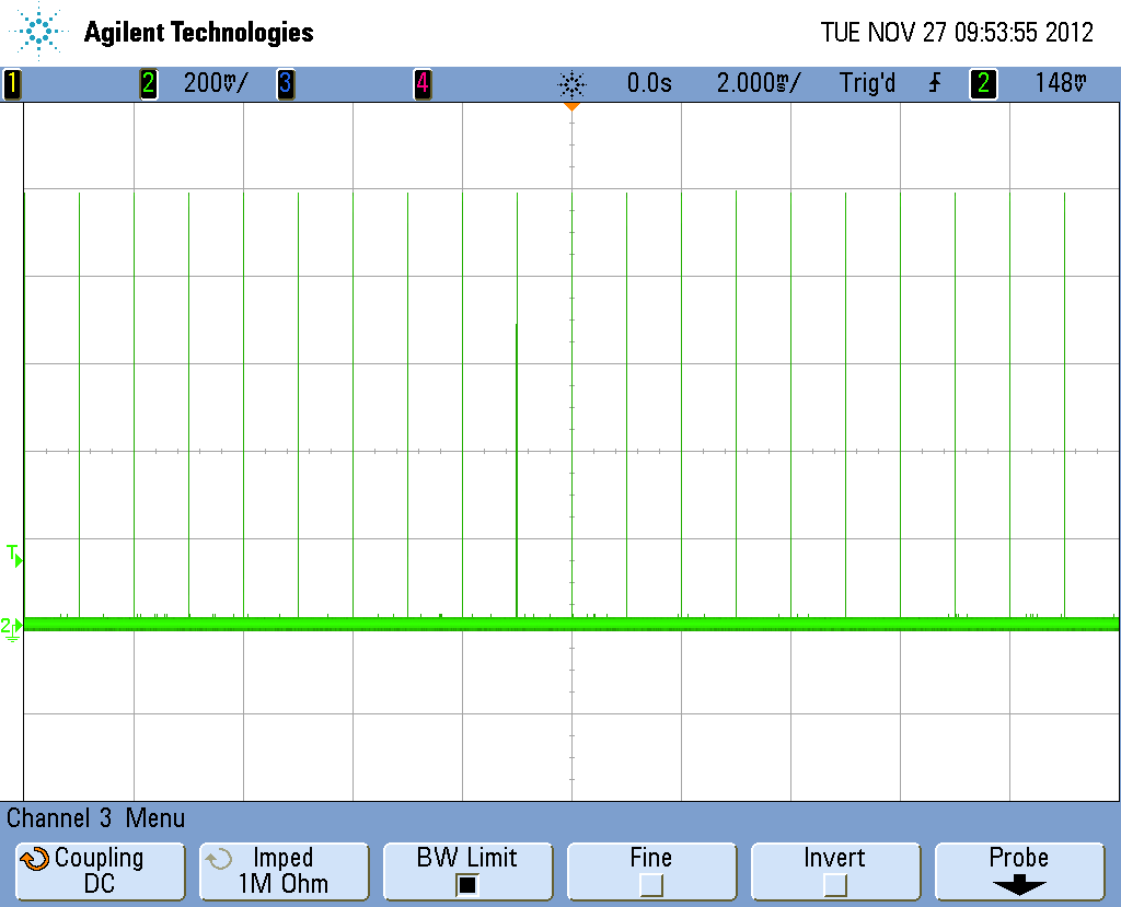
Figure 14- Mode 7-1KHz trigger with WS0 ( Suppression level 0 )
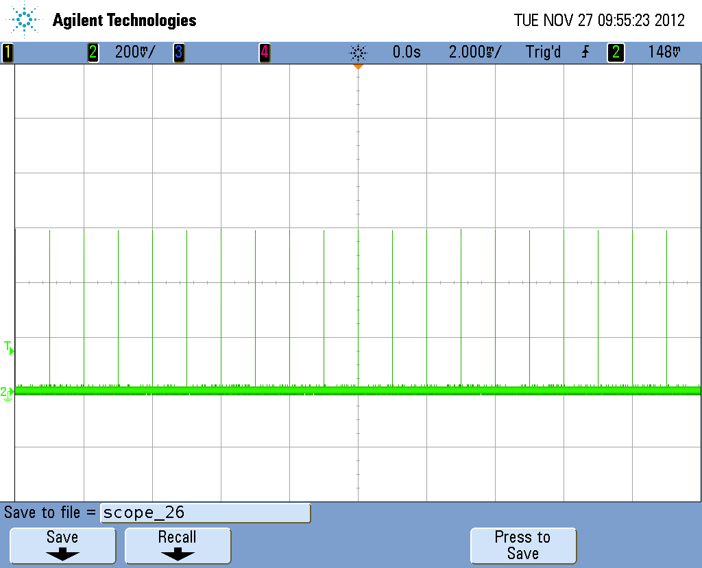
Figure 15- Mode 7-1KHz trigger with WS3000 ( Suppression level 3000 )
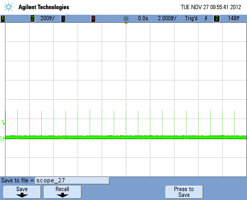
Figure 16- Mode 7-1KHz trigger with WS4000 ( Suppression level 4000 )
Chopper Operation
The MLPC Pulse Controller contains a hardware divider that uses the FL ( 30MHz Nominal ) input to generate internal pulse triggers. The 30MHz signal is divided by 2 and the resulting 15MHz signal is fed to programmable hardware divider. The MG command sets the divide rate in a range from 15 to 9999 which results in internal trigger rates of 1MHZ down to 1.5KHz.
The controller also contains a software implemented chopper that is used for generating a range of triggers from 5KHZ down to 0.152Hz. When in chopper mode, the hardware divider ( WG ) is set to 1500 to produce a 10KHZ trigger rate which is then divided by the value programmed using the WH command. The range of values for the chopper rate are 2 to 65535 which result in internal trigger rates of 5KHZ down to 0.152Hz.
For example,
WH10000 results in a rate of 1Hz
WH1000 results in a rate of 10Hz
WH100 results in a rate of 100Hz
WH10 results in a rate of 1KHz
To enter the chopper mode, simply write to the WH register with the desired division setting. The controller will then set WG at 1500 to produce the 10KHz internal signal which is then chopped to produce the desired trigger rate.
To exit chopper mode, simply write to the WG register. The controller will set the chopper rate to 1 ( in 1) which essentially disables it. The controller will be in hardware divide mode.
The chopper is functional in modes 2, 3, 4 and 5 only. Do not enable the chopper in other modes.
About Long Pulse Bursts
When producing long pulse bursts ( maximum recommended is 300ns ) the maximum rep rate should be keep at 100KHz or lower. The two waveforms below demonstrate why this limit should be observed. Each waveform shows a 300ns pulse with suppression at 4000 and a suppression time of 200ns. 5 pulse packets are sent at 100KHz in Figure 17 and at 500KHz in Figure 18. The suppression voltage is shown in purple and one can observe in the Figure 17 that the suppression voltage has time to recover after each burst, where in Figure 18, the suppression voltage does not have enough time to recover. This results in successive bursts having a lower level of suppression.
The zoom in each waveform shows the first burst in the packet.
Channel 4 ( RED ) is showing MPU interrupt activity for diagnostic purposes.
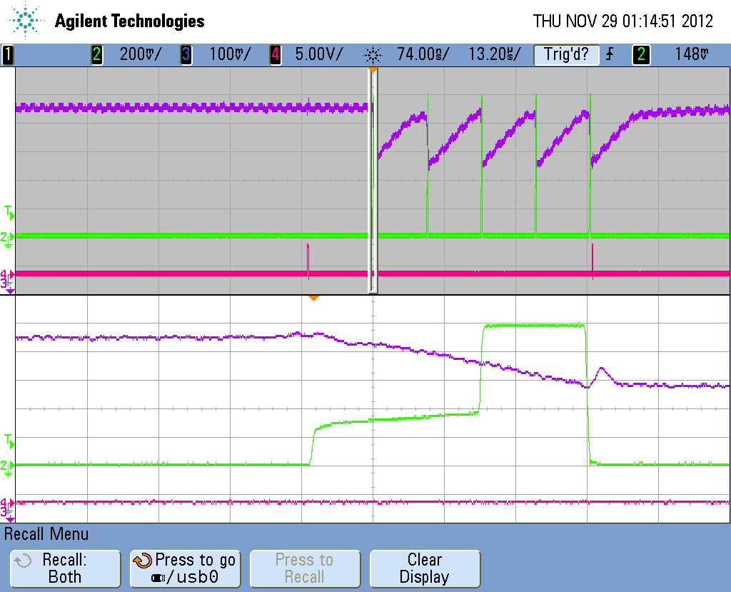
Figure 17 - WC150 WA100 WG150 ( 100KHz Rep rate ) 5 pulse packet - Full suppression recovery.
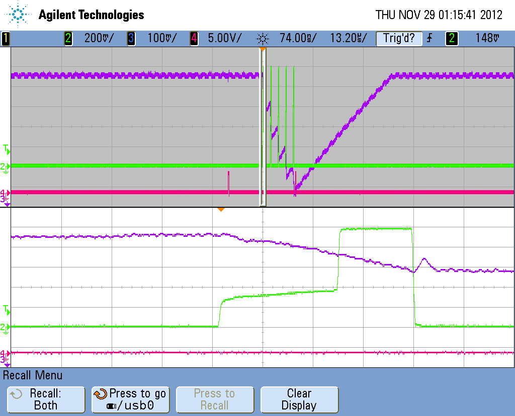
Figure 18 - WC150 WA100 WG30 ( 500 KHz Rep rate ) 5 pulse packet - No suppression recovery
Ensuring T signal does not effect suppression integrity.
The MPLC, when operating in pulse-burst mode with suppression, produces a waveform with both an analog and digital component that are added by the output amplifier to produce the A output signal. The analog component of the waveform is the section where suppression is occurring. The noise on the analog voltage during this time must be kept as low as possible as this is where the modulator is being operated in a quasi linear mode. The MLPC is designed to ensure no digital activity occurs during this time, however, it is possible for the controller to be programmed to start the T signal in this interval. The T signal timing is controlled by the WB command. Figure 19 shows the WB command set such that the T signal transitions during the suppression stage of the burst waveform shown. Note that a small negative dip in the suppression level can be observed at this time. Figure 20 shows the same waveform with the T signal placed after the suppression phase and so no anomaly is observed.
IMPORTANT: Ensure the WB setting ( T output delay) is set to the value of WA ( or greater ) which is the suppression time to avoid this anomaly. WA may also be set to zero to ensure the T signal transitions before suppression begins.
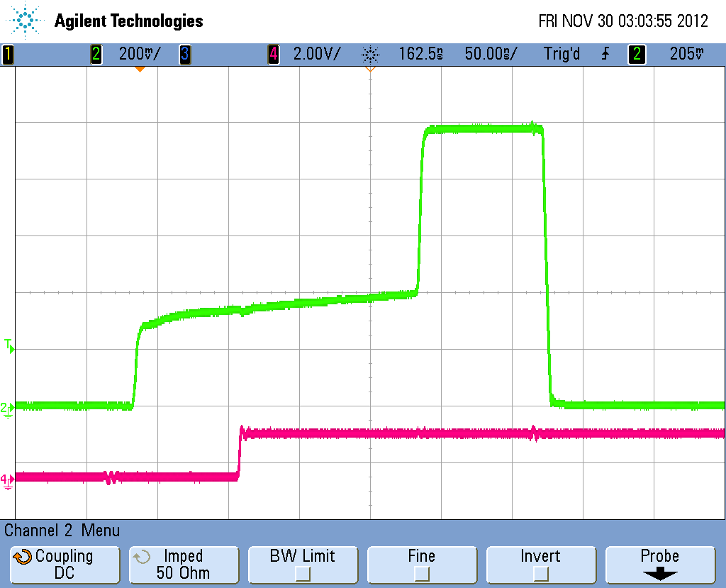
Figure 19 - WA delay causes dip in suppression voltage. ( T signal in RED )
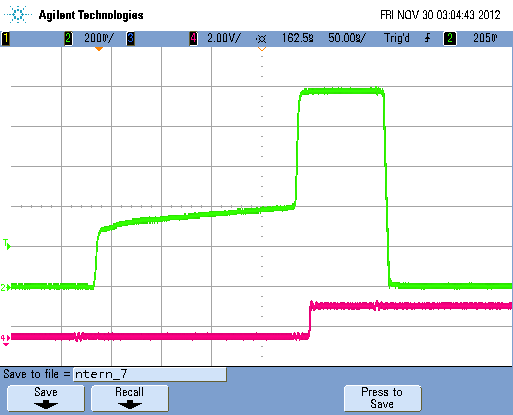
Figure 20 - WA delay set out of suppression range. ( T signal in RED )
About single pulses and effects high suppression has on width.
Figure 21 shows a typical output pulse produced with a WC setting of 15 ( 30ns) with no suppression ( WS0 ). In this configuration an output pulse of 30nS, with an amplitude of 1V into 50 ohms is generated.
Figure 22 shows the same pulse with the suppression added of WS3550 to produce a pulse with an amplitude of 400mV. Note that the width has been reduced to 18.2ns. This is due to the fact that the output amplifier rise time is reduced, and initial response time is increased, with high suppression settings.
One possible solution to this anomaly is to use a setting of WC19 ( 38ns) which actually produces a pulse of 26.3ns ( Figure 23 ) under high suppression.
Figure 24 shows the same waveform with suppression removed is 38.6ns in width. Provided the WD ( phase of A signal ) is set accordingly, gating of more than one seed pulse can be avoided.
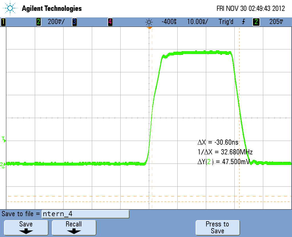
Figure 21 - WC15( 30ns ), WS0( 1 V ), WG150 ( 100KHZ rep rate ) Mode 7
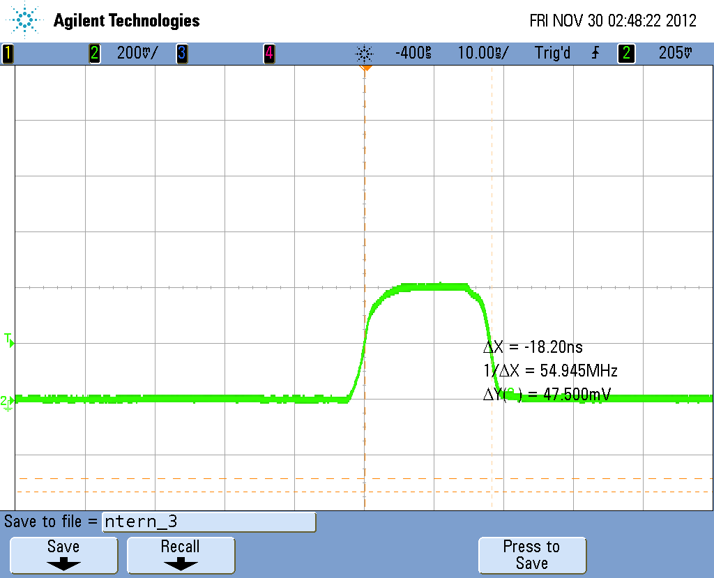
Figure 22 - WC15( 30ns ), WS3550 ( 400mV ), WG150 ( 100KHZ rep rate ) Mode 7
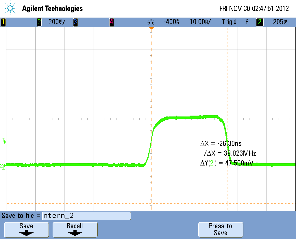
Figure 23 - WC19( 38ns ), WS3550 ( 400mV ), WG150 ( 100KHZ rep rate ) Mode 7
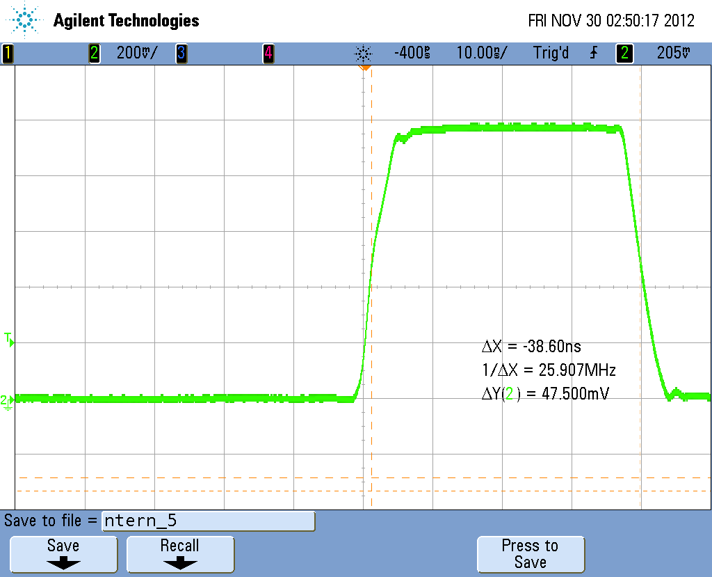
Figure 24 - WC19( 38ns ), WS0 ( 1 V ), WG150 ( 100KHZ rep rate ) Mode 7
Why does WA have a minimum value of 15?
The WA command sets the time that the output amplifier waits before being driven into saturation. In other words it determines the length of time the output amplifier operates in the linear ( suppression) mode. If this value is set to less than 15 , it will disable suppression features for all pulse widths including single-pulse mode. The default ( power-on) setting for WA is 15.