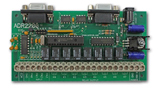
 Relay I/O interface, has four digital input lines ( PA0,PA1,PA2,PA3 ) that can be
used to provide an interrupt to the host when an input is pulled low. Additionally, a
sixteen bit trigger register can be loaded to provide an interrupt when the event counter
reaches a specific count. All inputs have built in pull-up resistors tied to the 5 volt
supply. When interrupts are enabled, bringing any line low or when the event counter
reaches the trigger value, a two digit value is returned to the host. The first digit is
the board address ( 0 - 9 ) and the second identifies the source of the interrupt ( 1 for
PA0, 2 for PA1, 3 for PA2, 4 for PA3 and 5 for an event counter match). For example;
Relay I/O interface, has four digital input lines ( PA0,PA1,PA2,PA3 ) that can be
used to provide an interrupt to the host when an input is pulled low. Additionally, a
sixteen bit trigger register can be loaded to provide an interrupt when the event counter
reaches a specific count. All inputs have built in pull-up resistors tied to the 5 volt
supply. When interrupts are enabled, bringing any line low or when the event counter
reaches the trigger value, a two digit value is returned to the host. The first digit is
the board address ( 0 - 9 ) and the second identifies the source of the interrupt ( 1 for
PA0, 2 for PA1, 3 for PA2, 4 for PA3 and 5 for an event counter match). For example;
- an interrupt on PA0 on board 0 returns
01
- an event counter match on board 3 returns
35
Interrupts generated at the same instant will be returned with highest priority given to PA0, followed by PA1,PA2,PA3 and lastly, an event counter match. All interrupts are disabled on power up.
The Interrupt commands are;
IE Enables all interrupts
ID Disables all interrupts.
IS Returns status of interrupts ( 0 if disabled, 1 if enabled )
Tlnnnnn Loads event counter trigger value ( nnnnn = 0 to 65536 )
TS Returns event counter trigger value.
Notes To Operation.
1. The IE command is used to enable all interrupts, however, the event counter match interrupt is not enabled unless a trigger value other than 0 is loaded into the trigger register using the TLnnnnn command. The trigger register is loaded with 0 on power-up. To disable the event counter match interrupt an any time, load the trigger register with 0 using the TLnnnnn command.
2. The IS ( interrupt status ) command should be used following an ID ( interrupt disable ) command to verify interrupts have been disabled. This may be required in cases where there is a possibility of an interrupt being generated when the ID command is issued. The primary communication used by ADR2000 series interfaces is Half-Duplex RS485 and interrupt data may collide with the ID command resulting in the ID command not being received by the ADR2200.
3. Once an interrupt is generated and data is sent to the host, no further interrupts will be generated by that particular input unless the IE command is sent. When interrupt data is sent to the host, that input is masked until the IE command is re-sent to un-mask the input.
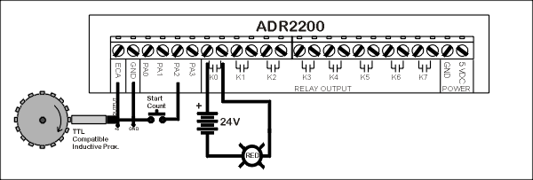
The following example shows use of the interrupts using Visual BASIC. This is a counter application which is initiated when an operator activates the " Start Count " button which is connected to PA2. At this point the event counter counts the pulses from the TTL compatible proximity detector and energizes K0 when a count of 160 is reached.
Private Sub Start_Click()
Rem Ensure Relay K0 is
off.
MSComm1.Output =
"RK0" + Chr (13)
Rem Enable interrupts.
MSComm1.Output =
"IE" + Chr (13)
Rem Wait for interrupt
from switch.
Do
Dummy = DoEvents()
Loop Until
MSComm.InBufferCount >= 3
Rem Display interrupt
in text window. ( Empties
input buffer )
Text1.Text =
MSComm1.input
Rem Clear event
counter
MSComm1.Output =
"CE" + Chr (13)
Rem Load trigger
register with 160 ( also enables counter interrupt )
MSComm1.Output =
"TL160" + Chr (13)
Rem Wait for interrupt
from event counter.
Do
Dummy = DoEvents()
Loop Until
MSComm.InBufferCount >= 3
Rem Display interrupt
in text window. ( Empties input buffer )
Text1.Text =
MSComm1.input
Rem Energize relay K0
( Turns on RED lamp.)
MSComm1.Output =
"SK0" + Chr (13)
End Sub
Notes on
operation of program.
1. Waiting for interrupts requires a loop until 3 characters (
Interrupt Data + CR ) are received by the serial input buffer.
2. Interrupt data is retrieved to empty the input buffer and
displayed in a text window for troubleshooting purposes.
3. Interrupt data can be read as a variable and tested to
determine source of interrupt. In this example it was not required as only one interrupt
was possible at one time. The counter interrupt ( 05 ) was not enabled until
the switch interrupt ( 03 ) was received.
Loop Until
MSComm.InBufferCount >= 3
Rem Display interrupt
in text window. ( Empties
input buffer )
Text1.Text =
MSComm1.input
Rem Clear event
counter
MSComm1.Output =
"CE" + Chr (13)
Rem Load trigger
register with 160 ( also enables counter interrupt )
MSComm1.Output =
"TL160" + Chr (13)
Rem Wait for interrupt
from event counter.
Do
Dummy = DoEvents()
Loop Until
MSComm.InBufferCount >= 3
Rem Display interrupt
in text window. ( Empties input buffer )
Text1.Text =
MSComm1.input
Rem Energize relay K0
( Turns on RED lamp.)
MSComm1.Output =
"SK0" + Chr (13)
End Sub
Notes on
operation of program.
1. Waiting for interrupts requires a loop until 3 characters (
Interrupt Data + CR ) are received by the serial input buffer.
2. Interrupt data is retrieved to empty the input buffer and
displayed in a text window for troubleshooting purposes.
3. Interrupt data can be read as a variable and tested to
determine source of interrupt. In this example it was not required as only one interrupt
was possible at one time. The counter interrupt ( 05 ) was not enabled until
the switch interrupt ( 03 ) was received.
Loop Until
MSComm.InBufferCount >= 3
Rem Display interrupt
in text window. ( Empties input buffer )
Text1.Text =
MSComm1.input
Rem Energize relay K0
( Turns on RED lamp.)
MSComm1.Output =
"SK0" + Chr (13)
End Sub
Notes on
operation of program.
1. Waiting for interrupts requires a loop until 3 characters (
Interrupt Data + CR ) are received by the serial input buffer.
2. Interrupt data is retrieved to empty the input buffer and
displayed in a text window for troubleshooting purposes.
3. Interrupt data can be read as a variable and tested to
determine source of interrupt. In this example it was not required as only one interrupt
was possible at one time. The counter interrupt ( 05 ) was not enabled until
the switch interrupt ( 03 ) was received.