|
The ADU71 USB to Current Output Interface is a USB bus powered current loop source for driving 4-20mA
or 0-20mA input devices. The ADU71 can also be used with external resistors to
provide 1-5VDC, 0-5VDC or 0-10VDC signals for variable frequency drives, valves etc. The ADU71 internally generated 24VDC loop supply eliminates the need for an external loop power supply. This low-cost USB to Current Output Interface is easy to use with VB, and Visual C++ or .NET via standard HID drivers included with Windows 98,2000,XP,7,8. A mini-driver ( DLL )* is also provided allowing control using standard ASCII commands using familiar readfile , writefile commands. The ADU71 includes a 10' USB cable and is available in a flange mount enclosure with a DIN rail mount option.
Connecting external devices to the ADU71 is
relatively simple, however, caution must be taken
because the ADU71 has an internal 24VDC loop power
supply and so,
no external loop supply should be used with the ADU71
LOOP output.
1. Connecting the
ADU71 to 4-20mA Current Input
Devices.
The first connection example shows the correct method
to connect a device which has a 4-20mA current loop
input. Figure 1 shows the correct connnections.
Note that the "+" of the LOOP output is connected to the
"+" of the device under control and, the "-" of
the LOOP output is connected to the "-" of the device
under control as shown in Figure 1.
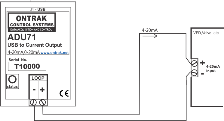
Figure1: ADU71 connections to a 4-20mA current
loop input device such as a variable frequency drive (
VFD ) motor controller.
If the application requires two current input devices
to be powered in the loop they can be connected in
series as shown in Figure 2.
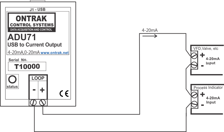
Figure 2: ADU71 connections to multiple 4-20mA
current
loop input devices.
2. Connecting the
ADU71 to Voltage Input
Devices.
Voltage input devices can also be connected to the
ADU71 LOOP output provided the input connections are
terminated with an appropriate resistor. For 1-5VDC
input devices the input should be shunted with a 250 ohm
resistor to convert the 4-20mA current signal to a
1-5VDC signal as shown in Figure 3.
CAUTION:
Ensure the resistor is correctly and firmly connected to
the device input terminals. If the resistor is not
correctly connected, or open circuit, the ADU71 will
apply 24VDC to the input of the device under control
when the ADU71 loop current is enabled. This may
damage the input circuitry of the device under control.

Figure 3 : ADU71 driving a 1-5VDC input VFD or
valve.
If the device under control has a 0-5VDC input, the
connections are identical to Figure 3, however, the
ADU71 LOOP is programmed to provide 0-20mA to the loop
as shown in Figure 4.

Figure 4 : ADU71 driving a 0-5VDC input VFD or
valve.
If the device under control
requires a 0-10VDC input, a
500 ohm resistor ( or two 250 ohm resistors in series)
should be shunted across the input terminals of the
device under control. The ADU71 LOOP is then
programmed to provide 0-20mA to the loop as shown in
Figure 5.
CAUTION:
Ensure the resistor is correctly and firmly connected to
the device input terminals. If the resistor is not
correctly connected, or open circuit, the ADU71 will
apply 24VDC to the input of the device under control
when the ADU71 loop current is enabled. This may
damage the input circuitry of the device under control.
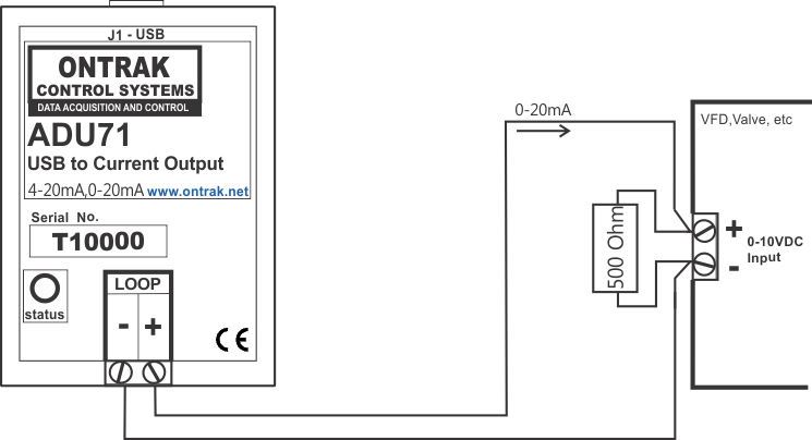
Figure 5 : ADU71 driving a 0-10VDC input VFD or
valve.
Multiple voltage input devices can also be connected
to the ADU71 LOOP output provided each is shunted by the
appropriate resistor as shown in Figure 6.
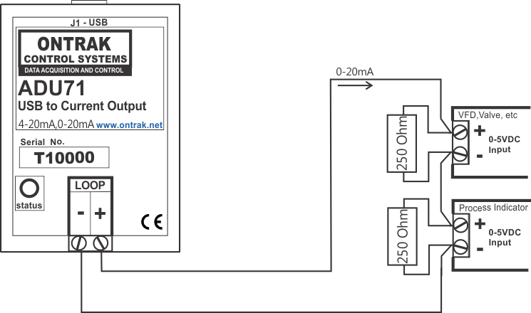
Figure 6 : ADU71 driving multiple
0-5VDC voltage input devices with 0-20mA output.
View
all Ontrak Products. |