|
Pulse Width Modulation outputs produce digital waveforms that can be
used as low-cost digital-to-analog converters with only a few external components. To
convert the PWM signal to an analog voltage, a low-pass filter is used. Concerns when
selecting the components for the filter are noise components inherent in digital
waveforms. PWM signals contain strong noise components at the PWM frequency and at odd
harmonics of that frequency. PWM modules in all ADR products can operate at 9.76 Khz thus
the strong noise components are at 9.76Khz and higher. An RC filter with a bandwith
many magnitudes lower than the PWM frequency will keep noise to a minimum. We
recommend a filter bandwidth of 30Hz since the ADR devices are serial based and
producing higher bandwidth outputs is not practical. The load on the filter should be kept
as low as possible and use of a voltage follower buffer amplifier may be required in
some applications.
The Bottom Line...
To convert a PWM output to an analog voltage use a low-pass filter
with an R = 4.7K and C = 1.0uF. This gives a bandwidth of 30Hz. Ensure the PWM frequency
for the ADR product is set to 9.76Khz. ( The ADR2100 default is 610Hz ).
Note:
The ADR2100
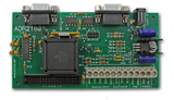 has space on the PCB to install the RC components. For PWMA use
position R6 and C6. For PWMB, use positions R7 and C7. If it is desired to keep the
RC filter components off the PCB, remove the pull-down resistors shipped with the
ADR2100 in positions C6 and C7 before connecting RC filter. has space on the PCB to install the RC components. For PWMA use
position R6 and C6. For PWMB, use positions R7 and C7. If it is desired to keep the
RC filter components off the PCB, remove the pull-down resistors shipped with the
ADR2100 in positions C6 and C7 before connecting RC filter.
Ref. Application Note AN538 , Microchip Technology Inc.
Back to Applications Page |